BLOG
Designing Hardware at the Speed of Software
July 28, 2026 · Rick Rothbart, Prototype Researcher, and Graham Wenz, Director of Engineering, Orbital Industries
The iteration problem
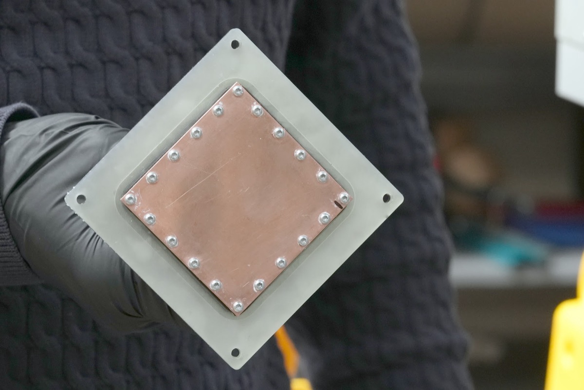
As chip TDPs climb from 700 watts to over 2,000 watts and rising rack power densities push the industry toward direct-to-chip liquid cooling, the engineering question has shifted. It's no longer whether to adopt liquid cooling but how quickly you can develop and qualify cold plate designs that keep pace with accelerating hardware roadmaps. Each new GPU generation brings different die sizes, package geometries, and thermal design power targets, and a cold plate that performed well on one chip may underperform on the next. At data center scale, where thousands of chips sit behind shared coolant distribution infrastructure, the cold plate serves as a critical interface between the silicon and the facility's thermal management system.
Two-phase cooling, where the coolant undergoes a phase change from liquid to vapor at the heated surface, offers substantially higher heat transfer coefficients than single-phase approaches, but introduces additional design complexity around boiling stability, vapor management, and flow distribution.
The design cycle for this kind of hardware has always been slow, and every step compounds the delay. Research alone is measured in weeks. Nucleate boiling correlations span decades of publications, from Chen (1966) to Tolubinsky and Kostanchuk (1970) to Kurul and Podowski (1990), and surveying which of them apply to your geometry and fluid, then running preliminary calculations, can consume the better part of a month.
Then you need a physical part. If you don't have machining capability in house, you go external expecting a quick turnaround, only to hit delays outside your technical control: scheduling queues, tooling lead times, communication overhead. If you do have the capability, it still takes three to five days to dial in feeds, speeds, and fixturing, with some CNC operations running 24 hours straight. We routinely work with features well under 100 microns, pillar separations that push machines to their limits.
A single pass through the full loop, from concept to test data, takes a month or more, and each pass typically teaches you one thing: this fin spacing was too tight, that flow rate was too low, or the interface material didn't seat properly. Every lesson costs a full cycle. With GPU generations turning over on 12 to 18 month cadences, a month-long iteration cycle leaves you a handful of design passes before the thermal targets change entirely, which means you either compress the cycle or make each cycle count for more.
We've been working to compress this cycle using AI-driven design generation, automated CFD simulation, and a tight feedback loop between computational and physical testing.
AI in the design loop
We use our AI agent, CurieOS, as a core part of the engineering workflow. The most immediate impact is on research, calculation, and data analysis, where work that used to take days or weeks now takes hours: surveying boiling correlations, identifying relevant heat transfer models, sizing channels for a target flow regime, and processing raw test rig output that we'd previously have worked through by hand. CurieOS compiles, synthesizes, and calculates at a pace that lets us spend our time on engineering judgment rather than information gathering.
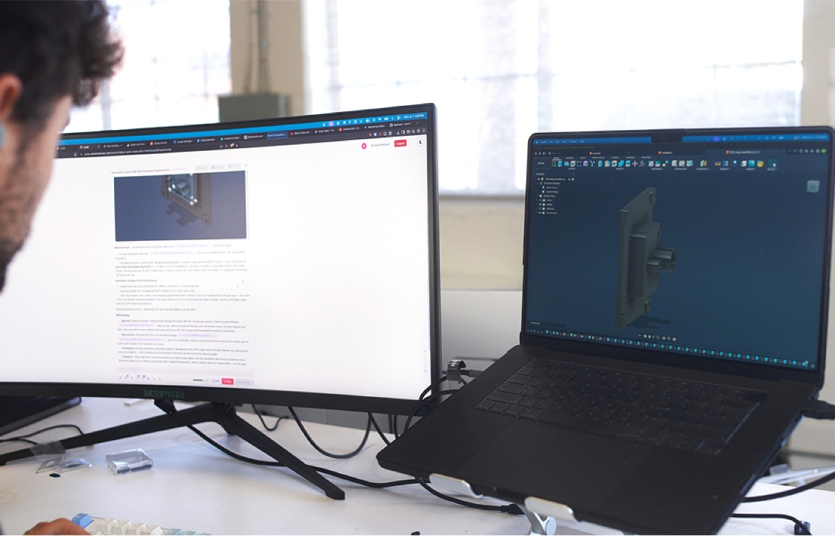
The deeper value emerges when AI starts participating in the design itself. Our cold plate program spans simultaneous research fronts: surface features, jet impingement nozzle design, and computational simulation. We're also using AI to generate voxel-based cold plate architectures, geometries that would be difficult to design manually, which we'll be prototyping with a copper 3D printing manufacturing partner. Each front generates candidates evaluated against the same performance targets: keeping a high-power chip within its thermal envelope while managing pressure drop and flow distribution across a combinatorial space of fin or pin pitch, height, thickness, nozzle hydraulic diameter, standoff distance, and flow configuration, all of which interact nonlinearly. Rather than an engineer manually exploring one geometry at a time, CurieOS reasons across the full design space, proposes candidates informed by published correlations and our own test data, and evaluates them computationally before any metal gets cut.
Case study: the jet impingement lid
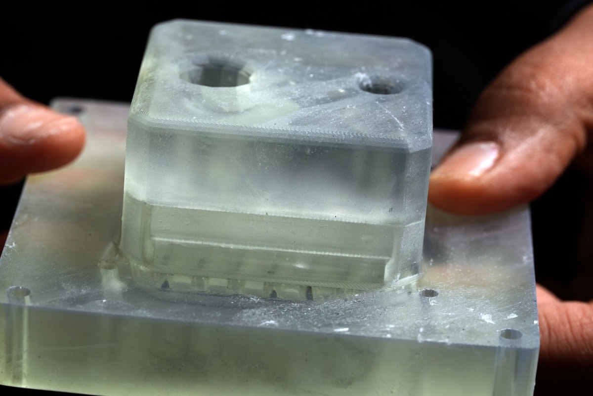
Here's a recent example from our two-phase cold plate program. We were designing a jet impingement lid to direct coolant jets onto the cold plate surface, disrupting vapor film formation during nucleate boiling and improving heat transfer coefficients. The design space is large, with hole diameter, pitch, standoff height, and flow distribution all interacting nonlinearly.
V1: Human-designed with AI research support. One of our engineers used CurieOS for a targeted literature review on jet impingement cooling, surveying correlations, identifying design heuristics, and running preliminary calculations. With that foundation, they designed a first-generation lid balancing our engineering constraints against the published evidence, which we manufactured and tested.
V2: AI-designed with human review. We fed the same problem context (constraints, objectives, V1 test data) back to the AI and asked it to propose an improved design with minimal human steering, and the result surprised us. Rather than uniform cylindrical holes, it proposed a necked, funnel-shaped geometry at the jet outlets: the converging profile accelerates the flow and reduces pressure drop across the lid, one of our key constraints. It's the kind of refinement an experienced engineer might reach after several iterations, but the AI got there in minutes by reasoning across the full design space.
V3: Validated and evolved. Based on the AI's suggestions and our own engineering review, we converged on a V3 inlet design that we've since fabricated and tested. CurieOS also surfaced an entirely different flow architecture that none of us had initially considered. We're now building all variants in parallel, evaluating them computationally before committing to physical prototypes.
The takeaway from this progression is about throughput: the number of viable design candidates an engineering team can evaluate in a given time window increases substantially when AI handles the literature synthesis, parametric reasoning, and preliminary calculations, freeing engineers to focus on the judgment calls that require physical intuition and domain experience.
Simulation as code
The gap between "I think this design will work" and "I know this design works" has traditionally required manufacturing and testing physical prototypes. We've been closing it with a fully code-driven CFD pipeline.
Cold plate geometries are defined parametrically, so a design is a set of numbers rather than a static CAD file. Changing a fin pitch or channel width and regenerating the geometry is trivial, which means we can produce and evaluate many design variations without manual setup per run. We're building a multi-fidelity simulation pipeline with three tiers: fast single-phase correlations for initial screening, an Eulerian two-fluid boiling model for design-loop evaluation (10-30x costlier but applicable to arbitrary geometries), and full Volume of Fluid simulations that resolve the liquid-vapor interface directly when the cheaper tiers disagree. The first two tiers are operational today; the full three-tier workflow is where we're heading.
Calibrated to our hardware. We've calibrated the pipeline against hundreds of experimental runs on our own test rigs, spanning our standard test matrix of 150-2000 watts heat input and flow rates from 0.1 to 1.5 liters per minute at atmospheric pressure. Our steady-state boiling simulator now predicts cold plate surface temperature to within a few degrees of measured values across the conditions we've calibrated against. The default bubble departure correlations, calibrated for water on standard surfaces, were off by roughly 20°C for our coolant and surface combination, since departure diameters can differ by an order of magnitude between fluid-surface pairings. This kind of system-specific calibration is the difference between a simulation you can trust for design decisions and one that merely looks plausible.
The pipeline outputs peak surface temperature, pressure drop, thermal resistance, and convergence quality for each candidate, allowing us to evaluate dozens of geometries computationally and build only the most promising. The design cycle becomes: simulate many, build few, test the best.
Closing the loop
Simulation doesn't replace physical testing: interface resistances, manufacturing tolerances, flow maldistribution, and boiling instabilities are hard to capture in any model. What we're building is a tighter loop between the physical and digital worlds.
- Design (AI-accelerated): CurieOS generates parametric geometries as CadQuery code, informed by literature, past test data, and engineering constraints.
- Simulate (automated CFD): Geometries flow through the CFD pipeline, with the best candidates surfacing by predicted performance.
- Build: CNC machining (down to 50-micron features on our CNC mills) and 3D printing for rapid prototyping of manifolds and lids.
- Test: Physical experiments on test rigs, collecting thermal and hydraulic data across the operating envelope.
- Calibrate and feed back: Test results tighten simulation parameters and flow back into the design graph, informing the next round of AI-generated candidates.
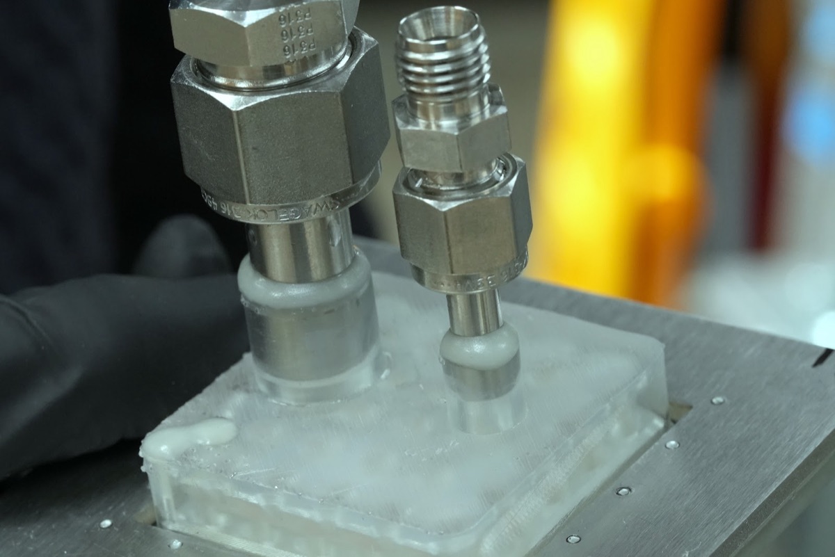
The iteration involves two distinct loops: physical fit (does the part assemble, do interfaces mate, do fittings seal?) and performance (does the cold plate hit its thermal targets under real operating conditions?). On the simulation side, we're building neural surrogate models: graph neural networks trained on our CFD data that predict temperature and pressure fields on unseen geometries in seconds rather than hours, fast enough to sit inside an optimization loop.
We've also built a graph-based platform that connects design goals to parametric geometries, test data, CFD results, and the decisions they informed. When a simulation finishes or an experiment completes, performance metrics are automatically attached to the corresponding design, and discrepancies between simulation predictions and measured performance become context for the next design iteration. Engineers, managers, and technicians each see the information relevant to them without anyone manually packaging status updates.
Scaling up
Cold plates gave us a forcing function: real thermal targets driven by production chip TDPs, real machining constraints, and unambiguous measurements to close the loop against. But the workflow we've built, combining AI-accelerated research, parametric geometry as code, automated simulation, and a connected design graph, applies wherever the design space is large, simulation is available, and physical testing is expensive.
As we scale from single-chip test rigs to rack-level cooling systems, the methodology extends directly to component layouts, fluid line sizing, tubing routing, and three-dimensional arrangement optimization under real physical constraints. The challenges at rack scale differ in scale but not in kind. Flow distribution across multiple cold plates, pressure drop management through an entire coolant distribution unit, and thermal uniformity across chips with different power profiles all lend themselves to the same combination of parametric geometry and automated simulation. Rapid iteration on cold plate designs also matters at the facility planning level, where cooling infrastructure decisions are made months before servers arrive and the margin for error on thermal performance is narrow.
Recent academic work has demonstrated that LLMs can generate parametric CAD code and automate CFD simulation setup, but these capabilities remain isolated demonstrations. We're assembling the full loop, where geometry generation, physics simulation, and design iteration operate as a single end-to-end system. With the right physical and virtual infrastructure in place, hardware development can move at a pace the traditional cycle never allowed.